Photograph the nut shape separately
Many replacement problems come from the nut shape, not the screw thread itself. Take a front view, side view, and angled top view of the nut so the supplier can see the flange, oil hole, mounting face, and nut length.
Split the shape into two families first: flanged (square or round flange carrying the mounting holes) and cylindrical (clamped in a housing or fitted as a unit). A flanged nut is then either square or round, with different hole counts and angles. Once that is clear, hole distance and center height become meaningful.
Flange direction must match the machine mount
The same screw diameter and lead may still fail if the flange direction is different. The photo should show which side of the nut has the flange, nut direction, whether the mounting face points toward the motor side, and whether dust protection or a special boss exists.
The quickest way to settle direction is one photo of the nut sitting on the machine's original nut seat, shot from the motor side. That single frame usually says more about direction than ten separate photos.
Mounting hole positions need a square photo
Photograph mounting hole positions perpendicular to the flange face and keep all holes in frame. Hole distance, hole diameter, counterbore, or threaded hole positions should be clear. If center height can be measured, state the center height and reference surface.
Three shooting rules: keep the lens perpendicular to the flange (an angled shot distorts hole distance), light it so reflections do not cover the hole edges, and get every hole in one frame — one missing hole and the hole pattern cannot be judged.
Use photos with a ruler or caliper
Use photos with a ruler or caliper for hole distance, outer diameter, flange thickness, and nut length. Do not cover the hole edge or mounting face, and keep caliper readings readable so the supplier does not estimate by photo scale.
How to take the two decisive measurements:
- Hole distance: measure centre to centre between two holes. With more holes, give the adjacent spacing and the pattern (for example four holes on a square, symmetric spacing).
- Center height: measure from the nut axis perpendicular to the mounting face, and state whether the reference is the flange back or the mounting face.
Nut photo RFQ checklist
- Front view, side view, angled top view of the nut, plus one full screw photo.
- Flange direction, mounting face direction, oil hole position, and dust protection.
- Mounting hole positions, hole distance, hole diameter, counterbore, or threaded hole details.
- Center height, nut length, flange thickness, and nut housing space in the machine.
FAQ
If the photos are clear, do I still need to measure hole distance? Yes. Clear photos show structure and direction, but hole distance and center height have to be measured; a nut that looks identical but sits 1 mm off will not enter the original seat.
Is nut shape the same thing as the screw model? No. A 1605 or 2005 describes screw diameter and lead; nut shape, flange form and hole pattern are separate information, and a replacement needs both.
Can I quote a nut without the screw? The nut can be quoted, but end machining and overall length wait on the screw dimensions, so photograph them together.
Next step
Turn this guide into an RFQ
When the specification direction is clear, send the details below together with quantity, lead time, and packing requirements.
Include these details
- Old-part overall length, thread length, diameter, lead, and nut style.
- Full old-part photos, both end details, nut flange, and mounting-hole photos.
- Machine use, whether it is a like-for-like replacement, quantity, and lead time.
Category
Related Technical Guides
Continue with similar buyer questions
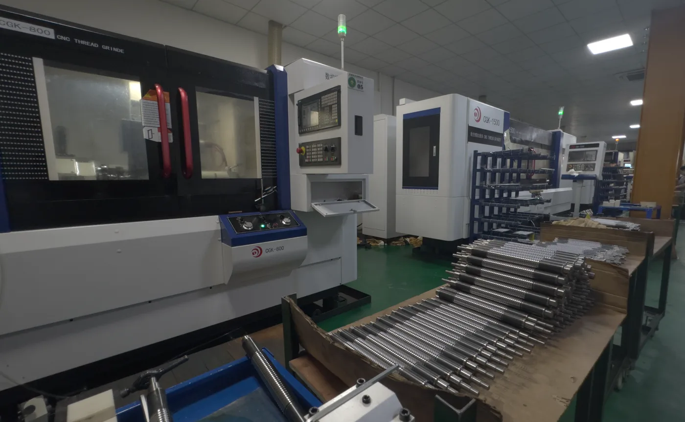
How to Prepare a Ball Screw RFQ When You Only Have Old Part Photos
Old-part photos can start the RFQ, but they must be paired with key dimensions and installation details so quotation is not guesswork.
Send old-part photo RFQ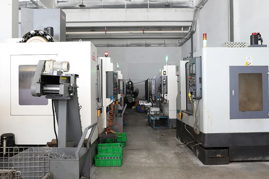
What to Confirm Before Replacing a Ball Screw in CNC Repair
CNC repair replacement should not be ordered by model number alone because axis, travel, end machining, and old part photos affect installation fit.
Send CNC repair replacement details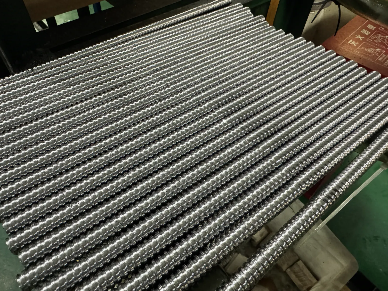
How to Measure a Replacement Ball Screw: 6 Dimensions
Record diameter, lead, overall length, travel, and end steps before sending old-part photos or samples.
Send replacement dimensions